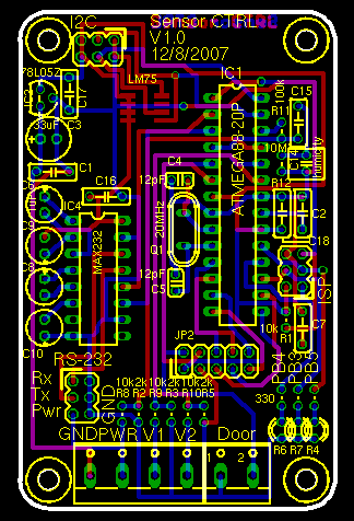
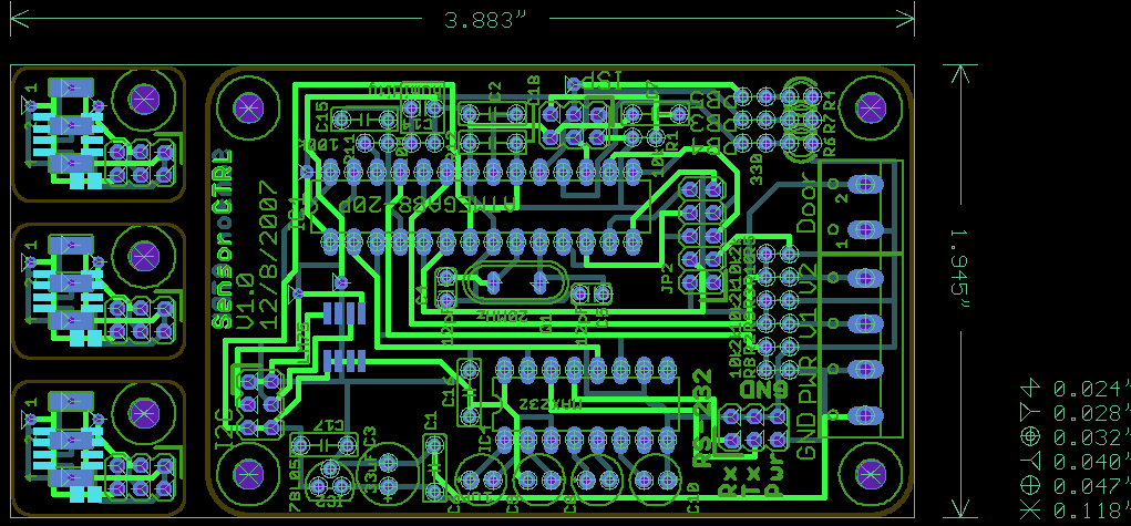
PCB layout of the sensor controller
NrVissing.Net is the community driven WISP that I'm doing tech for, we are in the middle of expanding our backhaul to 80 MB/s via a 6 km, two leg, 801.11a wireless link.
The new wireless link means that we will have several remote, outdoor routers that need constant environmental monitoring to ensure that condensation doesn't form and that we discover leaking enclosures before damage is done.
The sensors we need to keep an eye on are:
Nothing exists with a pricetag that we can afford, so that's where I come in...
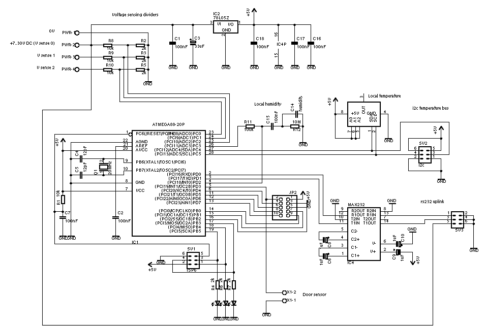

PCB layout of the sensor controller
The temperature sensor used is the LM75, it has 3 address pins allowing up to 8 sensors on a single i2c bus, so I've constructed a simple carrier board that can have the address "programmed" with a soldering iron:
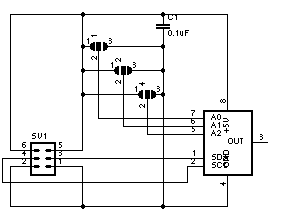
The LM75 carrier schematic
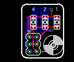
PCB layout of the lm75 carrier board
Gold Phoenix doesn't want to panelize my designs, that means that I have to combine the gerbers and drill files for my two designs into one panel that GP can do their step/repeat magic on.
Before panelization can take place the layouts need to be turned into gerber and drill files, this is done mostly like Sparkfuns Eagle tutorial suggests. and I even use their silk_gen.ulp and SFE-Special.cam files.
The process of panelization is handled by a program called gerbmerge, which is controlled in part by sensor-lm75.layout (see the tarball at the bottom of this page for details):
Row {
  Col {
   lm75 Rotate
   lm75 Rotate
   lm75 Rotate
  }
  ctrl Rotate
}
The configuration above yields the following layout:
Panelized controller and lm75 carrier
This layout means that we'll get 3 lm75 carriers per sensor controller, which turns out to be around the number we need.
Others have used Eagle to create the panel, but I think this is a terrible idea as that means that going back and tweaking one layout means redoing a lot of manual work, I've found that automating the panelization work with gerbmerge to be very useful in this regard.
You can read more about what I did with the layout on my Gold Phoenix vs. Olimex page.
All the files used in this project are available here: sensor-ctrl.tar.gz [112K], under the GPL.
The files contained in the tarball are:
| lm75-carrier/lm75-carrier.sch | Schematic for the lm75 carrier |
| lm75-carrier/lm75-carrier.brd | PCB for the lm75 carrier |
| lm75-carrier/jumper.lbr | Modified Eagle solderjumper lib with a via in the center pad. |
| lm75-carrier/lm75.lbr | lm75 lib |
| sensor-ctrl/sensor-ctrl.sch | Schematic for the controller |
| sensor-ctrl/sensor-ctrl.brd | PCB for the controller |
| sensor-ctrl/lm75.lbr | That lm75 again. |
| silk_gen.ulp | The silk screen generator, lifted from Sparkfuns Eagle tutorial. |
| goldenphoenix.cam | The SFE-special.cam file, lifted from Sparkfuns Eagle tutorial. |
| sensor-panel/sensor-lm75.layout | Layout file for gerbmerge. |
| sensor-panel/sensor-lm75.cfg | Configuration file for gerbmerge, controls stuff like inter-board spacing. |
| sensor-panel/make | A simple shell script to keep the needed postprocessing commands in one place. |
| sensor-panel/lm75-ctrl.txt | The note I sent along to GP. |
| sensor-panel/olimix.make | Call gerbmerge to generate an Olimex friendly panel. |
| sensor-panel/sensor-lm75.olimex.layout | Olimex friendly layout. |